Starter System
SAFETY FIRST: Protective gloves and eyewear are recommended at this point.
Troubleshooting
If the electric starter does not turn perform the following checks. You will need a digital multimeter for these tests.
If the starter motor turns but doesn't turn the engine over inspect the starter clutch. See the Starter Clutch topic for more information.
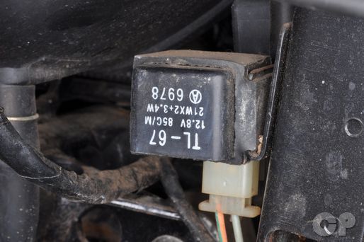
1. Turn the ignition switch to the on position, shift the transmission into neutral and pull in the clutch lever. Make sure the engine stop switch is in the run position. Hit the starter button and listen for the starter relay to click. The starter relay is located on the left side of the motorcycle.
If the starter relay clicks move on to step 2. If the starter relay doesn't click move to step 3.
2. Remove the starter motor, using a jumper wire apply 12 volts DC to the starter motor and if it does not turn over it is a bad starter. If the starter motor does turn check for the following faults.
Turn Signal Switch/ Side Stand Relay
Bad Connector
Pinched or Broken Wires
3. Set your digital multimeter to read voltage. Touch the positive meter lead to the yellow/green starter relay connector and the negative to the black/white starter relay connector. Hit the starter button and check for voltage.
If there is voltage check the starter relay. If there is no voltage check for the following faults.
Turn Signal Switch/ Side Stand Relay
Bad Connector
Pinched or Broken Wires
4. If the starter motor will run in neutral, but not in any gear, and the side stand is up check the side stand switch.
If the side stand switch check out. Look for a bad connector or a pinched or broken wire in the harness.
Starter Relay
Remove the upper fairing. See the Upper Fairings topic for more information.


Loosen the negative battery cable screw with a #3 Phillips head screwdriver or 10 mm socket. Disconnect the cable from the battery.


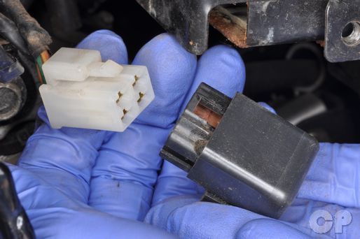
Remove the starter relay cover.
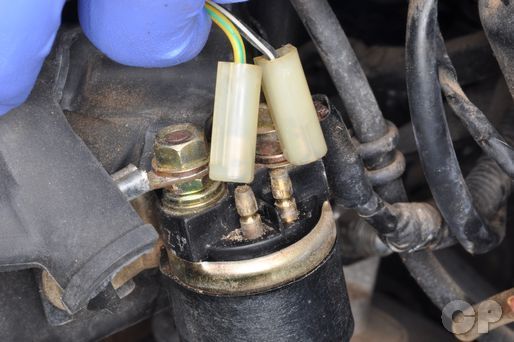
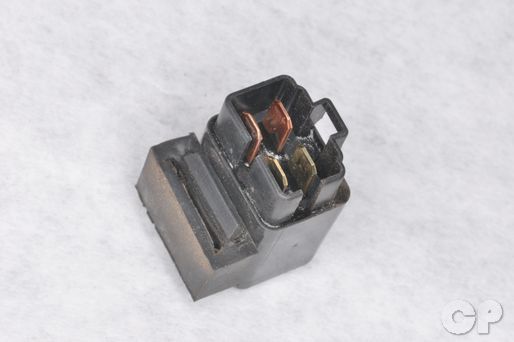
Use a multimeter to check the starter relay.
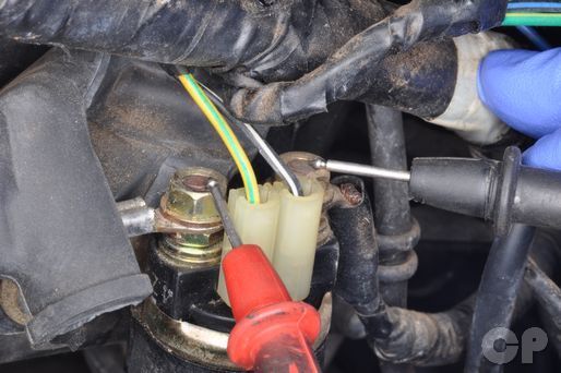
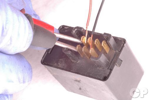
Place the positive and negative probes on the starter relay terminals and turn the ignition switch to "on" position. Squeeze in the clutch lever and push the starter button to check for continuity.
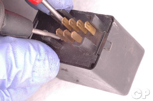
Remove the leads from the starter relay terminals. Use a multimeter to measure resistance.
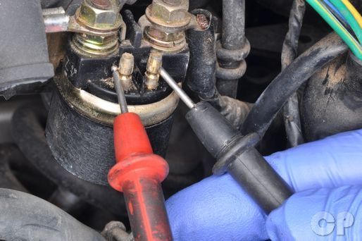
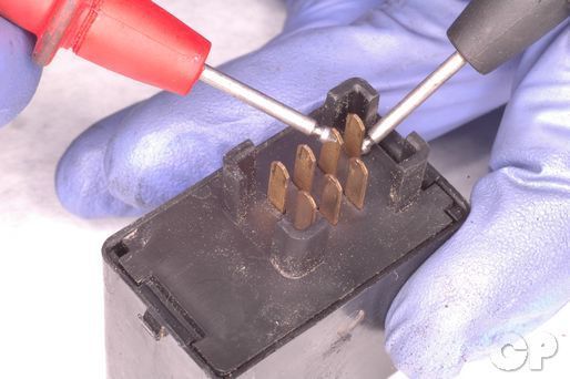
Check the resistance with the probes on the starter relay terminals as shown. Resistance should be within specified range.
(Starter Relay Resistance: 3 - 5 Ω)


Remove the starter relay leads with a 10 mm socket.


Remove the two starter relay switches with a #3 Phillips screwdriver.
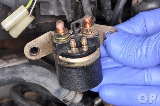
Remove the starter relay.
Turn Signal/ Side Stand Relay
Remove the seat to access the turn signal/ side stand relay. See the Upper Fairings topic for more information.


Remove the turn signal relay and disconnect the connector.


Remove the side stand relay from the mounting clip.
Disconnect the side stand relay connector.
Check for continuity between the terminals as shown. If there is not continuity check as described below.
Apply a 12 volt source to the relay as shown. The red wire indicates the positive pumper lead and the black wire represents the negative jumper lead. check for continuity between the terminals as show. If there is not continuity the relay must be replaced.
Diode Inspection
Set your multimeter to read volts.


Touch the meter probes to the terminal as shown. The reading should be between 1.4 and 1.5 volts.
Touch the meter probes to the terminal as shown. The reading should be between 0.4 and 0.6 volts.
Starter Motor
Removal
Remove the upper fairing. See the Upper Fairings topic for more information.
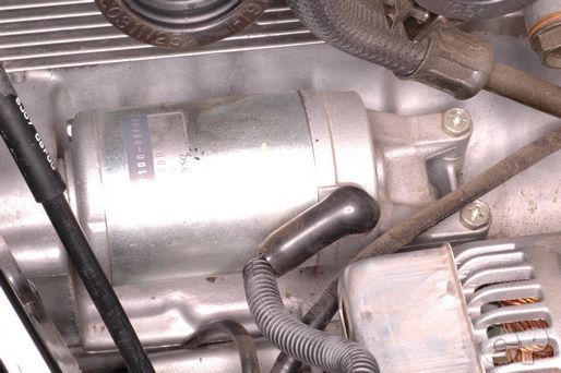


Loosen the starter motor lead wire bolt with an 8 mm socket. Remove the bolt and free the lead wire from the starter motor.
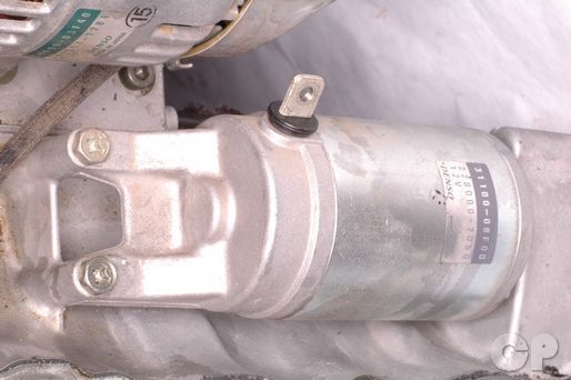


Remove the two starter motor bolts with a 10 mm socket.
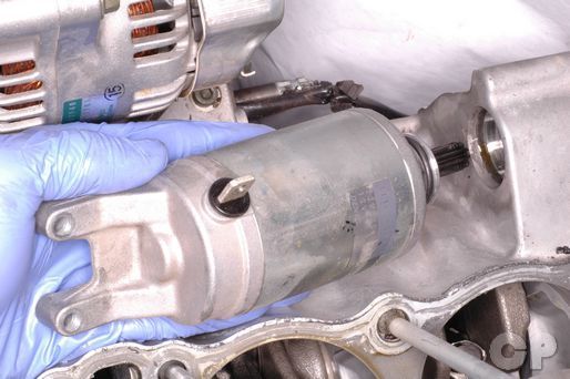
Remove the starter motor from the engine.
Disassembly and Inspection


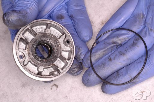
Remove the O-ring from the output end of the starter motor.


Loosen the two starter motor housing bolts with a 7 mm socket. Remove the housing bolts and O-rings


Slide off the output end cap. Remove the lock washer and shim.


Slide off the rear end cap. Remove the O-rings from the end caps.
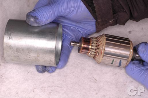
Remove the armature from the starter motor body.


Remove the brush holder mounting screws with a #2 Phillips screwdriver.
Slide the brushes out of their holders.


To remove the brush holder the solder must be melted with a soldering iron.


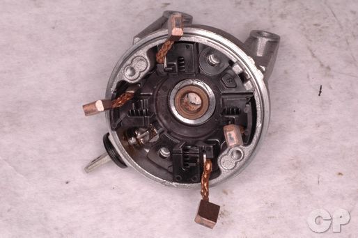
Remove the brush holder and brushes. Two of the brushes are removable and the other two brushes are fixed to the holder.


Inspect the brushes for wear and damage. Replace all the brushes if one is damage, excessively worn or out of service limit.
(Starter Motor Brush Service Limit: 6 mm or 0.2 in )
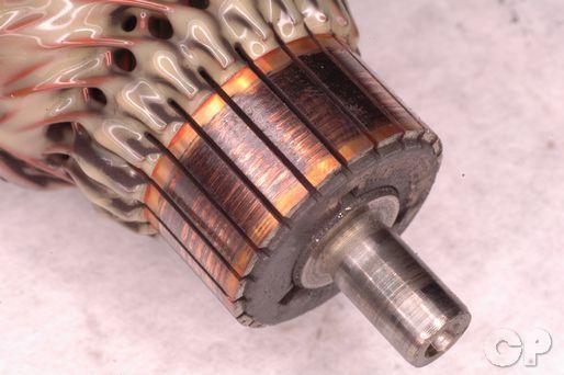
Inspect the armature for wear and discoloration. There should be a an undercut between the commutator strips.


The commutator strips can be cleaned up with fine grit sand paper or an emery cloth. Scrape out the insulator with a razor blade if the undercut is not present. Measure the commutator undercut to check it is within service limit.
(Starter Motor Commutator Undercut Service Limit: 0.2 mm or 0.008 in )
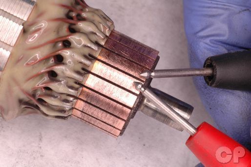
Using a digital multimeter set to ohms of resistance, touch one meter lead to any one commutator strip and touch the other meter lead to all of the other commutator strips one by one. Polarity of the meter leads does not matter. There should be continuity for all of the readings, if any readings show no continuity the armature must be replaced.
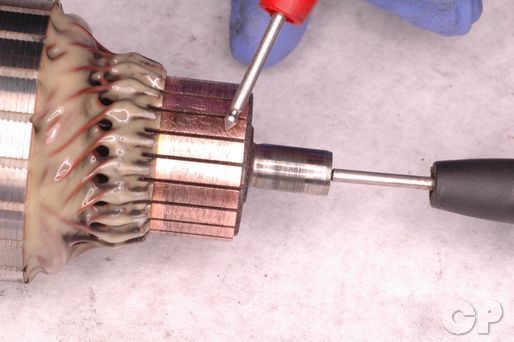
Using a digital multimeter set to ohms of resistance, touch one meter lead to any one commutator strip and touch the other meter lead to the steel shaft of the armature. Polarity of the meter leads doesn't matter, and you only need to check one of the commutator strips. There should be no continuity, if there is the armature must be replaced.
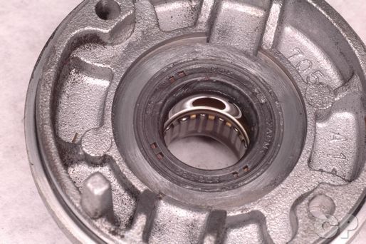
Inspect the bearing and seal in the out put side starter motor end cap. Replace the end cap if necessary.
Assembly
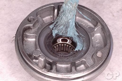
Lubricate the bearing seal with Suzuki "A" grease.
Suzuki Super Grease "A": 99000-25030


Lubricate the left end of the armature shaft with moly paste.
Suzuki Moly Paste: 99000-25140
Install the brushes into the brush holder.
Install the brush holder into the left starter motor cap. Install the two brush holder mounting screws and tighten them securely with a #2 Phillips screwdriver.

Solder the bushing holder to the terminal.
Install new O-rings onto the end caps. Apply a light coat of Suzuki "A" grease to the O-rings.
Suzuki Super Grease "A": 99000-25030

Install the armature into the starter motor body. Fit the lock washer into the output end cap and install the shim on the output end of the armature shaft.


Match the marks on the body with the end caps and install the end caps onto the starter motor body.
Apply blue Loctite to the threads of the two starter motor housing bolts. Install the starter motor housing bolts and O-rings. Tighten the bolts securely with a 7 mm socket.
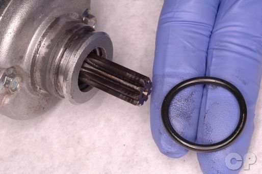
Install a new O-ring onto the output end of the starter motor. Coat the new O-ring in Suzuki "A" grease.
Suzuki Super Grease "A": 99000-25030
Installation
Insert the starter motor into place.
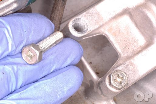

Insert the two starter motor mounting bolts and tighten them to specification with a 10 mm socket.
(Starter Motor Mounting Bolt Torque: 6 N-m or 4.5 lb-ft)
Install the starter motor lead to the starter motor. Tighten the bolt securely with an 8 mm socket. Slide the rubber cover into place.
Install the upper fairing. See the Upper Fairings topic for more information.
Copyright 2025 - Cyclepedia Press LLC

Note: If you are viewing this document offline be sure to visit the latest version online at http://www.cyclepedia.com before attempting any repairs. Updates are made without notice.